TRACKING & POSITIONING OF MOBILES IN TELECOMMUNICATION
  Mobile positioning technology has become an important area of research, for emergency as well as for commercial services. Mobile positioning in cellular networks will provide several services such as, locating stolen mobiles, emergency calls, different billing tariffs depending on where the call is originated, and methods to predict the user movement inside a region. The evolution to location-dependent services and applications in wireless systems continues to require the development of more accurate and reliable mobile positioning technologies. The major challenge to accurate location estimation is in creating techniques that yield acceptable performance when the direct path from the transmitter to the receiver is intermittently blocked. This is the Non-Line-Of-Sight (NLOS) problem, and it is known to be a major source of error since it systematically causes mobile to appear farther away from the base station (BS) than it actually is, thereby increasing the positioning error.
Recent demands from new applications require positioning capabilities of mobile telephones or other devices. The ability to obtain the geo-location of the Mobile Telephone (MT) in the cellular system allows the network operators to facilitate new services to the mobile users. The most immediate motivation for the cellular system to provide MT position is enhanced in accident emergency services. The positioning of the mobile user could provide services like
¢ Emergency service for subscriber safety.
¢ Location sensitive billing.
¢ Cellular Fraud detection.
¢ Intelligent transport system services.
¢ Efficient and effective network performance and management.

Location Tracking Curve Method
The method proposed by us for tracking the location of a mobile telephone using curves connecting the points where circles intersect one another, the circles radii being the distances between BSs and the mobile                                                                     telephone. The steps involved are:
a. Each base station nearer to a mobile telephone receives a predetermined signal from the mobile telephone and calculates the distance between the mobile telephone and the base station and the variances of time arrival of the signal at the base station;
b. A circle is drawn to have a radius being the distance and the coordinates of the base station being the center of the circle;
c. A pair of the first and the second base stations is selected among the base stations. A several location tracking curves connecting two intersection points between the selected circles corresponding to the first and the second base stations are drawn. One of the location tracking curves is selected using the variances of the first and the second base stations;
d. The steps c. and d. are repeated for the other pairs of the base stations;
e. The intersection points are obtained among the location tracking curves selected in step d. and e. and,
f. The location of the mobile telephone is determined using the coordinates of the intersection points obtained in step e.

The several location tracking curves are parts of circles with centers near to the base station with smaller variances between the first and the second base stations. The circles formed by the location tracking curves have the centers on a line connecting the coordinates of the first and the second base stations. The larger variances between the variances of the first and the second base stations are compared to the variances of the several location tracking curves, and one of the location tracking curves is selected according to the comparison result. The location coordinates of 
the mobile telephone are determined by averaging the coordinates of the


 Download Ppt in a Single File
CRUSOE PROCESSOR
  On board Transmeta Crusoe TM5800 Processor 800MHz
• Supports up to 512MB of DDR SDRAM via SODIMM Socket
• 10Mbps / 100Mbps Ethernet
• VIA VT82C686B Chipset
• AC ‘97 Audio Controller
• TTL Flat Panel Support
• TV Output NTSC/PAL
• Four USB 1.1 Ports
• Two Serial Ports
 Download Ppt in a Single File
 voice morphing
 Diamond Edition also presents a faster voice morphing algorithm, pro-looking interface, and numerous nickvoices, effects and packages of parody voices
which help users talk in the voices of many Hollywood stars and famous people.
 Download Ppt in a Single File

 Cutting edge at the cell edge
 Emerging broadband wireless systems, such as those based on IEEE 802.16 m or 3GPP LTE-A, will re-use spectrum in every sector (1 : 1 reuse) and maximize system spectrum efficiency. In so doing, the spectrum efficiency for cell-edge users is very poor in comparison with the system-wide average, and nomadic users located near the cell edge experience very low throughput. This is an important concern for India, where nomadic users constitute 85% of mobile phone users, urban cells are relatively small, and the fraction of cell-edge users is as high as 40%. The basic approach to improving cell-edge performance is the so-called fractional frequency reuse (FFR), where spectrum reuse is less than 1 : 1 for cell-edge users. However, techniques that mitigate/cancel interference can improve the spectrum efficiency of FFR. This paper reviews an integrated package of three techniques, proposed by CEWiT for inclusion in the international standards, which mitigate the impact of cell-edge co-channel interference in the downlink: two-dimensional phase offset diversity, inter-cell interference cancellation, and conjugate data repetition. The first two techniques employ multiple transmit antennas. The first and third are open-loop techniques, which will work for nomadic as well as high-speed users, while the second is closed-loop and involves base-station co-operation, and is suitable for nomadic users. All three techniques share the important feature that the transmit signal from each base station appears to be emanating from a single transmit antenna, enabling the use of low-complexity multi-antenna interference suppression algorithms at the receiver. The paper will discuss the performance of each technique, and also show that they can be employed together in a complementary manner to improve cell-edge performance.

Download Ppt in a Single File
 Orthogonal-Frequency-Division-Multiplexing
Orthogonal frequency-division multiplexing (OFDM) is a method of encoding digital data on multiple carrier frequencies. OFDM has developed into a popular scheme for wideband digital communication, whether wireless or over copper wires, used in applications such as digital television and audio broadcasting, DSL broadband internet access, wireless networks, and 4G mobile communications.
OFDM is essentially identical to coded OFDM (COFDM) and discrete multi-tone modulation (DMT), and is a frequency-division multiplexing (FDM) scheme used as a digital multi-carrier modulation method. A large number of closely spaced orthogonal sub-carrier signals are used to carry data. The data is divided into several parallel data streams or channels, one for each sub-carrier. Each sub-carrier is modulated with a conventional modulation scheme (such as quadrature amplitude modulation or phase-shift keying) at a low symbol rate, maintaining total data rates similar to conventional single-carrier modulation schemes in the same bandwidth.
Download Ppt in a Single File
Hide Blog Title & Description From Header On Blogger/Blogspot :
If you are on blogger platform and using any blogspot default template, you can notice your blog title and description appearing on the header area. If you are using a long blog title and a little more long blog description, then it will look odd. So, you need to remove those blog name and description info from the header area to make it look attractive. You may also like to exclude title & description and create a custom header for your blogger blogs. But remember that having title and description may boost your blog SEO values.

Remove Title & Description From Blogger Header :
  1. Log into your blogger profile and go to Dashboard.
  2. Navigate to Layout >> Edit HTML.
  3. Search for #Header h1 in your HTML code. If you don’t find this code, you may search for another piece of code #Header .description.
  4. Now insert display:none; at the end of the above code.
  5. Look at the below code to get the idea.
#header .description { /*<-- this is header description css*/
margin:5px 5px 0;
padding:15px 20px .25em;
line-height:1.2em;
display:none; /*<--Insert this line*/ }   
6. Save the template and you are done. 
Now your blog title and description will not show up in your blog’s 
header area. You may use any attractive image in your header and there 
will be no text to ruin the beauty of your blogger or blogspot blog 
header. 

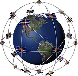
What is GPS?

satellite 
The Global Positioning System (GPS) is a satellite-based navigation system made up 
of a network of 24 satellites placed into orbit by the U.S.
Department of Defense. GPS was originally intended for military applications, but in the 1980s, th
e government made the system available for civilian use. GPS works in any weather conditions,
anywhere in the world, 24 hours a day. There are no subscription fees or setup charges to use GPS.

How it works

GPS satellites circle the earth twice a day in a very precise orbit
and transmit signal information to earth. GPS receivers take this information and use triangulation
to calculate the user's exact location. Essentially, the GPS receiver compares the time a signal was 
transmitted by a satellite with the time it was received. The time difference tells the GPS receiver
how far away the satellite is. Now, with distance measurements from a few more satellites,
the receiver can determine the user's position and display it on the unit's electronic map.
GPS Screens 
A GPS receiver must be locked on to the signal of at least three
satellites to calculate a 2D position (latitude and longitude) 
and track movement. With four or more satellites in view
, he receiver can determine the user's 3D position (latitude, longitude and altitude).
Once the user's position has been determined, the GPS unit can calculate other information,
such as speed, bearing, track, trip distance, distance to destination, sunrise and sunset time
and more.

How accurate is GPS?

Today's GPS receivers are extremely accurate, thanks to their parallel multi-channel design. 
Garmin's 12 parallel channel receivers are quick to lock onto satellites when first turned on 
and they maintain strong locks, even in dense foliage or urban settings with tall buildings. 
Certain atmospheric factors and other sources of error can affect the accuracy of GPS receivers
. Garmin® GPS receivers are accurate to within 15 meters on average.
GPS Signals 
Newer Garmin GPS receivers with WAAS (Wide Area Augmentation System) capability
can improve accuracy to less than three meters on average.
No additional equipment or fees are required to take advantage of WAAS.
Users can also get better accuracy with Differential GPS (DGPS), which corrects GPS signals
to within 
an average of three to five meters
. The U.S. Coast Guard operates the most common DGPS correction service.
This system consists of a network of towers that receive 
GPS signals and transmit a corrected signal by beacon transmitters. In order to get th
e corrected signal, users must have a differential beacon receiver and beacon antenna in addition
Satellite Diagramto their GPS.


The GPS satellite system

The 24 satellites that make up the GPS space segment are orbiting 
the earth about 12,000 miles above us. They are constantly moving, making two complete orbits
in less than 24 hours. These satellites are travelling at speeds of roughly 7,000 miles an hour.
GPS satellites are powered by solar energy. They have backup batteries onboard to keep them
running in 
the event of a solar eclipse, when there's no solar power. Small rocket boosters on each satellite 
keep
them flying in the correct path.
Here are some other interesting facts about the GPS satellites (also called NAVSTAR,
the official U.S. Department of Defense name for GPS):
  • The first GPS satellite was launched in 1978.
  • A full constellation of 24 satellites was achieved in 1994.
  • Each satellite is built to last about 10 years. Replacements are constantly being built
  • and launched into orbit.
  • A GPS satellite weighs approximately 2,000 pounds and is about 17 feet across with the
  • solar panels extended.
  • Transmitter power is only 50 watts or less.

What's the signal?

GPS satellites transmit two low power radio signals, designated L1 and L2.
Civilian GPS uses the L1 frequency of 1575.42 MHz in the UHF band. The
signals travel by line of sight, meaning they will pass through clouds, glass and 
plastic but will not go through most solid objects such as buildings and mountains.
A GPS signal contains three different bits of information - a pseudorandom code
, ephemeris data and almanac data. The pseudorandom code is simply an I.D. 
code that identifies which satellite is transmitting information. You can view this
number on your Garmin GPS unit's satellite page, as it identifies which satellites 
it's receiving.
Ephemeris data, which is constantly transmitted by each satellite, contains
important
information about the status of the satellite (healthy or unhealthy), current
date and time
. This part of the signal is essential for determining a position.
The almanac data tells the GPS receiver where each GPS satellite should
be at any time
throughout the day. Each satellite transmits almanac data showing the
orbital information 
for that satellite and for every other satellite in the system.
Blocked Signal Diagram

Sources of GPS signal errors

Factors that can degrade the GPS signal and thus affect accuracy include the
following:
  • Ionosphere and troposphere delays - The satellite signal slows as 
  • it passes through the atmosphere. The GPS system uses a built-in
  • model that calculates an average amount of delay to partially
  • correct for this type of error.
  • Signal multipath - This occurs when the GPS signal is reflected off 
  • objects such as tall buildings or large rock surfaces before it 
  • reaches the receiver. This increases the travel time of the signal
  • , thereby causing errors.
  • Receiver clock errors - A receiver's built-in clock is not as
  • accurate as the atomic clocks onboard the GPS satellites
  • . Therefore, it may have very slight timing errors.
  • Orbital errors - Also known as ephemeris errors,
  • these are inaccuracies of the satellite's reported location.
  • Number of satellites visible - The more satellites a GPS receiver 
  • can "see," the better the accuracy. Buildings, terrain, electronic
  • interference, or 
  • sometimes even dense foliage can block signal reception, causing 
  • position errors 
  • or possibly no position reading at all. GPS units typically will not
  • work indoors, underwater or underground.
  • Satellite geometry/shading - This refers to the relative position 
  • of the satellites at any 
  • given time. Ideal satellite geometry exists when the satellites are
  • located at wide angles 
  • relative to each other. Poor geometry results when the satellites 
  • are located in a line
  • or in a tight grouping.
  • Intentional degradation of the satellite signal - Selective Availability (SA) 
  • is an intentional 
  • degradation of the signal once imposed by the U.S
  • . Department 
  • of Defense. SA was intended to prevent military adversaries 
  • from using 
  • the highly accurate GPS signals. The government turned off SA
  • in May 2000,
  • which significantly improved the accuracy of civilian GPS receivers.
 Download Ppt in a Single File 
Click Here To Download
Copyright © 2012 Student guide.